View RSS Feed

Electrobes

Stand ReMod/Control Board plus other added Upgrades

Rate this Entry
So I finally decided to get off my butt and get some things done. I had, for the longest time, wanted to do several things that I just never got to:


1) Make my tank's info (Temp at the time) view-able WiFi and Cellular networks.


2) I wanted to have all my equipment (Not just the lights and temp stuff) controllable.


3) I was sick of my "Drawer" control board as the toll of pulling the drawer and dragging wires whenever I did it bugged me deeply. I wanted to have


a nice and clean control board that could hide but be easily accessible when needed.


The above is a tall order and I have graciously given a weekend, with the house to myself, to complete this project unhindered. (I am a house dad to


a two year old). I didn't have much time to plan this out well, so I needed to have a lot of measurements accurate, or just sheer dumb luck.


After obtaining what I thought were good measurements I went off to Home Depot and got the necessary materials to build the control board.


I started the project by removing the lights and semi-canopy off the tank.


Click image for larger version

Name:	IMG_3708 (Medium).JPG
Views:	175
Size:	51.9 KB
ID:	8464Click image for larger version

Name:	IMG_3709 (Medium).JPG
Views:	167
Size:	57.0 KB
ID:	8465Click image for larger version

Name:	IMG_3710 (Medium).JPG
Views:	165
Size:	56.7 KB
ID:	8466Click image for larger version

Name:	IMG_3712 (Medium).JPG
Views:	165
Size:	64.1 KB
ID:	8474


I wanted it to be fairly consistent with my current stand. The first thing that needed to be done was to remove all three bottom drawers of the


stand, and knock out the supports that let them slide in and out of the stand. I could only remove the first two, because I still had to remove the


equipment from the top (of the three) drawer.


Click image for larger version

Name:	IMG_3718 (Medium).JPG
Views:	172
Size:	90.1 KB
ID:	8467


The next part involved cutting off the storage part of each of the two drawers, and keeping only the faces, so that I could later attach them


together forming a door.


Click image for larger version

Name:	IMG_3705 (Medium).JPG
Views:	170
Size:	80.2 KB
ID:	8468Click image for larger version

Name:	IMG_3706 (Medium).JPG
Views:	147
Size:	69.2 KB
ID:	8469Click image for larger version

Name:	IMG_3707 (Medium).JPG
Views:	174
Size:	73.6 KB
ID:	8470


Before I could remove the drawer with the equipment, I had to remove the equipment! It's amazing how much stuff could fit in there!


Click image for larger version

Name:	IMG_3713 (Medium).JPG
Views:	165
Size:	65.8 KB
ID:	8471Click image for larger version

Name:	IMG_3714 (Medium).JPG
Views:	170
Size:	62.7 KB
ID:	8472Click image for larger version

Name:	IMG_3715 (Medium).JPG
Views:	163
Size:	70.2 KB
ID:	8473


I finally got the last drawer out, plus I was intermittently doing the control board. It involved a little black staining, and some bordering, but it


came out nice.

Click image for larger version

Name:	IMG_3703 (Medium).JPG
Views:	166
Size:	49.6 KB
ID:	8475Click image for larger version

Name:	IMG_3704 (Medium).JPG
Views:	155
Size:	45.8 KB
ID:	8476


Here's me gluing the border onto the back board.


Click image for larger version

Name:	IMG_3711 (Medium).JPG
Views:	178
Size:	58.7 KB
ID:	8477


I finally got the third drawer face and finished the "door".


Click image for larger version

Name:	IMG_3717 (Medium).JPG
Views:	159
Size:	78.8 KB
ID:	8478


Now it was time to add the equipment to the control board.


Click image for larger version

Name:	IMG_3719 (Medium).JPG
Views:	168
Size:	65.9 KB
ID:	8479Click image for larger version

Name:	IMG_3721 (Medium).JPG
Views:	172
Size:	84.1 KB
ID:	8480Click image for larger version

Name:	IMG_3722 (Medium).JPG
Views:	152
Size:	105.1 KB
ID:	8481Click image for larger version

Name:	IMG_3729 (Medium).JPG
Views:	174
Size:	87.7 KB
ID:	8482


Overall the project is a major success given a weekend's time. I am so stoked as I bought a year subsciption to dyndns, and I can now control all of


my equipment on my phone, given I have WiFi or am within range of a cell tower. My only project left is to add a doser controlled by the controller


via the pH probe. The tank suffers from a fairly low pH, and I want to remedy that by having the pH monitor control the flow of Kalk water, and the


ATO using regular RO/DI. I hope it works in keeping the pH stable.. and helps with keeping the Calcium and Alk up.. as they are often times too low


even with me adding additives fairly regularly.

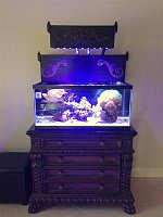
Here's how the tank looks now.

Click image for larger version

Name:	IMG_3745 (Medium).JPG
Views:	159
Size:	37.9 KB
ID:	8483Click image for larger version

Name:	IMG_3747 (Medium).JPG
Views:	175
Size:	37.3 KB
ID:	8484

Submit "Stand ReMod/Control Board plus other added Upgrades" to Digg Submit "Stand ReMod/Control Board plus other added Upgrades" to del.icio.us Submit "Stand ReMod/Control Board plus other added Upgrades" to StumbleUpon Submit "Stand ReMod/Control Board plus other added Upgrades" to Google

Updated 07-08-2013 at 01:55 PM by Electrobes (Forgot last two pics...)

Categories
New Additions , ‎ Electrical , ‎ DIY projects , ‎ Equipment

Comments

  1. melev's Avatar
    That came out really good! Your control board leans at an angle all the time then?
  2. Electrobes's Avatar
    Thanks Marc, and yep it leans back all the time for a funny reason... when I do my nightly ritual of staring at the tank with the moonlights on I am always sitting. That, and it leaning gave me more board to work with, so all the equipment is nice and spaced out.
  3. melev's Avatar
    I'd imagine it also lets you spool the wiring under and behind it.
  4. Electrobes's Avatar
    Yep!
  5. snorkeler's Avatar
    Very cool, neatly organized now. BTW beautiful tank stand + top covers. Your tank stand style is exquisite, inspiring.
  6. Electrobes's Avatar
    Thanks Snorkeler!